No More Tangles

Since we first drove the coupe nine months ago I’ve slowly been adding components to the car. First we had only the Tesla motor and it’s controller. That wiring was very clean and organized in the trunk. Then we added the gear selector up front. Then we added our ignition key, the electric parking brakes, our electric power steering and brake assist pump. Then we added brake lights and turn signals so we could drive her on the road. We added our computers to run the digital dash and gauges, and on and on…
Each new system would be added into the wiring, and each time things would get a bit messier, but there was no way to avoid this. Each of these systems that I had dreamed up had to be tested and refined before I knew if they would work as desired. I simply had to keep moving forward with this temporary wiring until the car was stable. That day has come, so the time to clean up all this temporary wiring has also finally come.
Start With a Plan
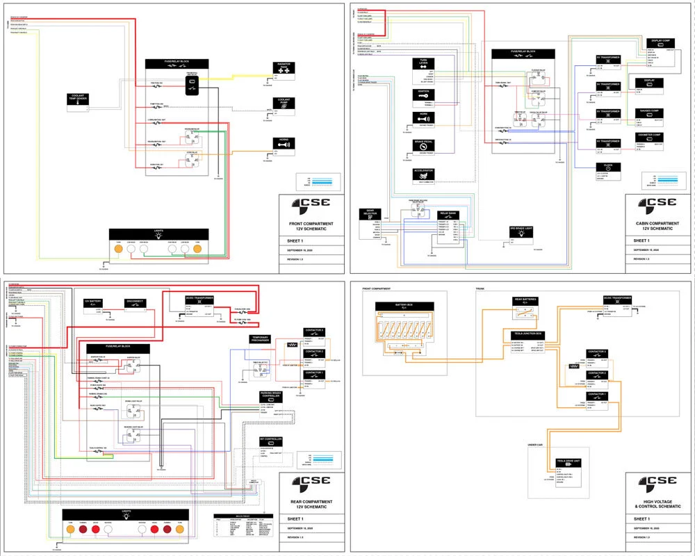
Over the last few months I'd been working on these wiring schematics. The first 3 sheets are the 12v systems and the last is the 320v Tesla system (Yes, these drawings are low resolution. Since they aren’t final, I don’t want anyone using them and blowing up their car). This represents everything in the car today. Not yet represented are power windows, stereo, electric sunroof, heating, air conditioning and more. All of which will be implemented literally “down the road”. It is important for me to test and refine these current systems over many miles before then adding in more conveniences.
The basic design of the system is to have three distributed Fuse/Relay boxes. One in the trunk, one in the footwell of the cabin, and one under the hood. Each of these would feed the items near them. This will make it easier for me to service, troubleshoot and add components in the future.
Start Up Front
I started up front with the box under the hood. A large 8 gauge wire feeds power to this box from the rear of the car. Other wires join along from the cabin such as the horn button, high beams, turn signals. This box then feeds our headlights, turn signals, horns, coolant pump and radiator fans.
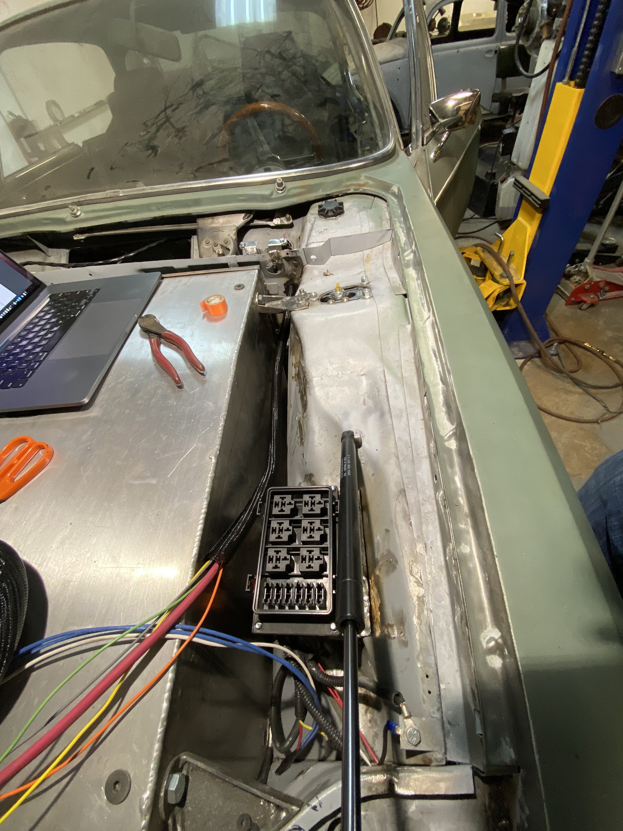
The front fuse box is installed under the hood. I’m either carefully referencing the schematics, or watching Netflix on my laptop.

Fuses and Relays are all wired in, along with a custom thermostat module which turns on our radiator fans at 90 degrees.
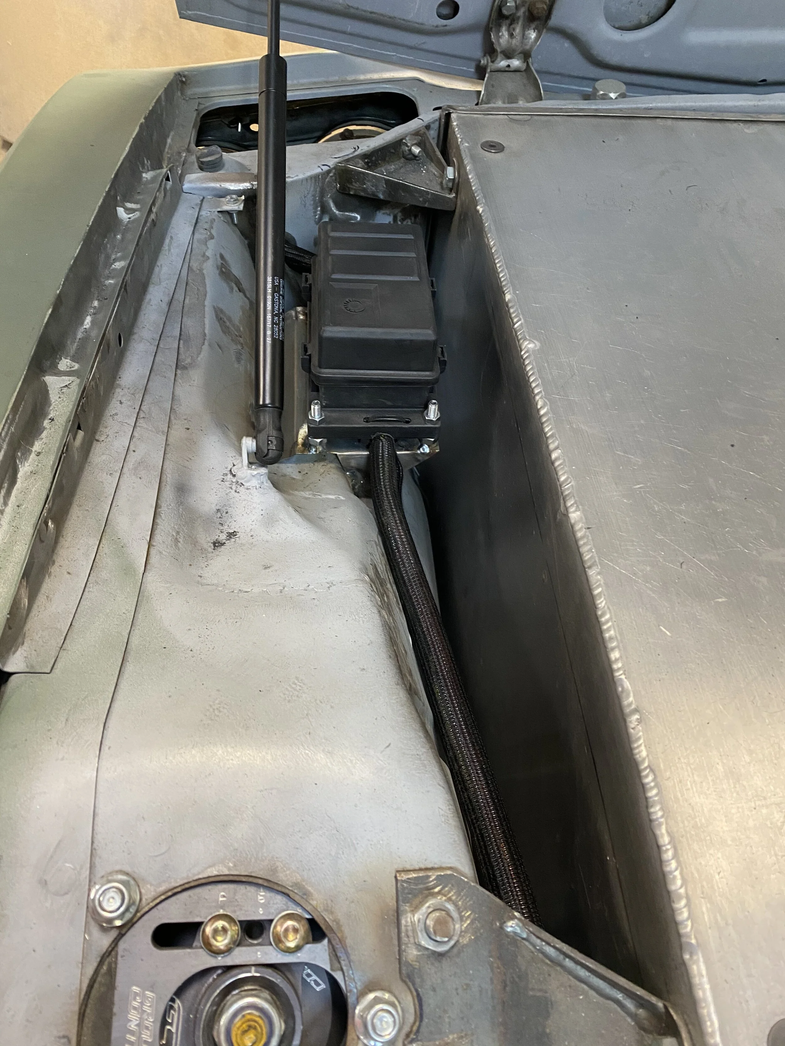
The box all closed up and ready to go. One clean wire loom runs past the large battery box under the hood.
Cleaning up the Trunk
Next I moved to the trunk which was a huge project. You saw the "Before" photo at the top of this post. This was the temporary wiring that evolved out of control as I was installing and testing each of the various systems. Now that they are all working and refined, I am ripping it all out to start over.
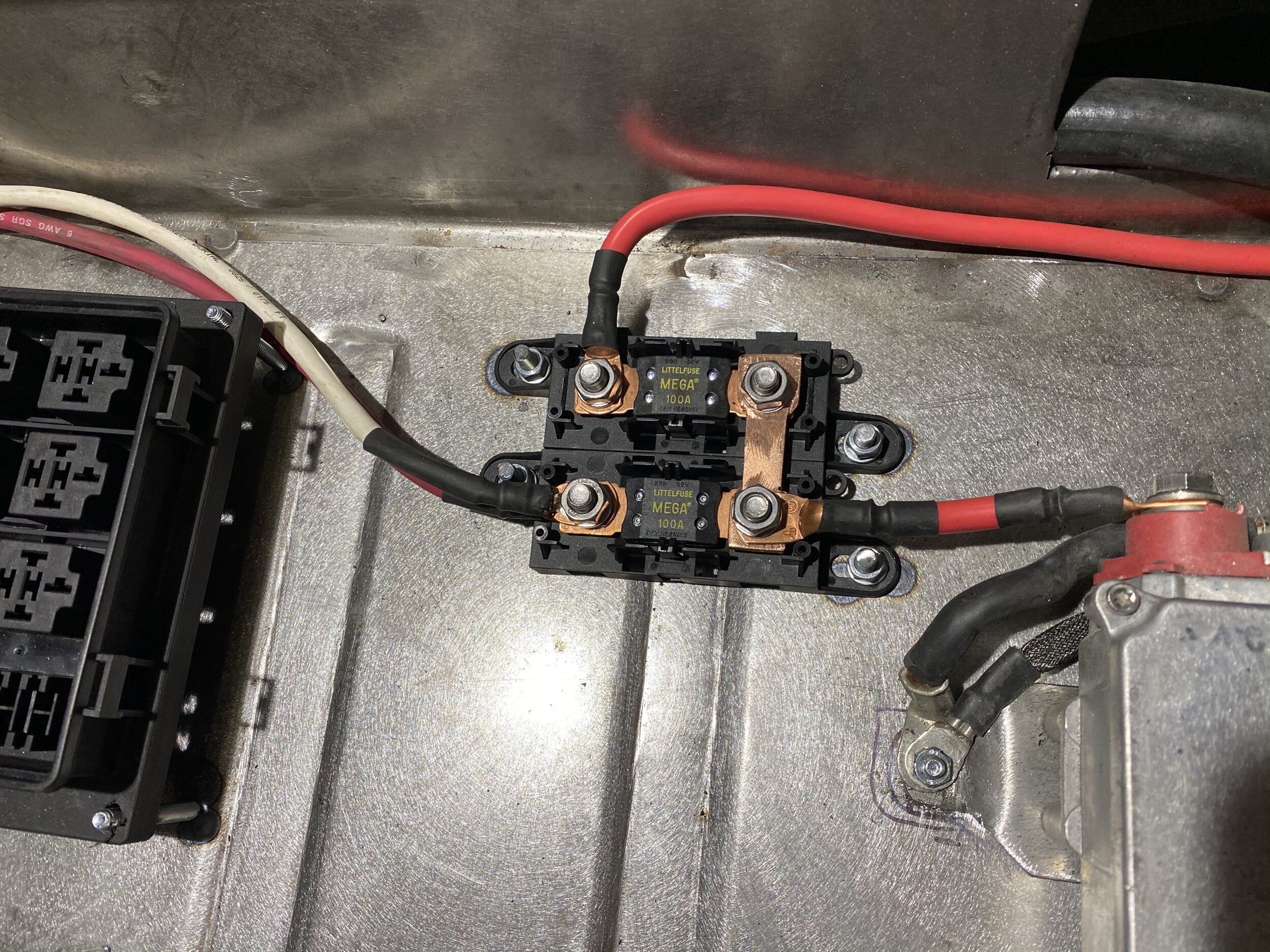
To the far right is our Tesla DC/DC transformer. It takes the 320 volts from the Tesla batteries and turns it into 12v to power all our automotive systems (think of it as our alternator). The transformer feeds a pair of 100 amp mega fuses. One of them runs directly to the BMW/Mini electric power steering pump. The other fuse feeds our three distributed fuse/relay boxes.

My motorcycle battery passes through a cutoff switch before entering the system. This switch will be accessible above the carpeted trunk floor. Since my clock and Raspberry Pi computer will always be running, I can disconnect if I am not driving the car for several days, or when I am working on the car.

I then wired up the 057 Tesla controller and my parking brake controller. In case you missed it, the Tesla has no "Park" function, and hand brakes don't typically lock the wheels, so I am using the same Brembo electric parking brakes that Tesla (and many other cars) use. When I put the shifter in park, the parking brakes activate automatically. Everything was loomed nicely and it is all tested and stable. This is a huge improvement over our “before” photo.


Even though I worked hard to make the wiring look nice, it will all be hidden under our false trunk floor. These panels create a nice usable trunk space. This will all be carpeted in the next week.
Into the Cabin and Center Console
Finally I moved to the cabin. This box has the turn signal relay, a VW "convenience" relay (for 3-flash lane change function) and fuses for the dash and console items. No photos of this fuse box as it’s pretty hidden behind the dash.

I wanted to modify the way the console installs. I added brackets which would allow me to remove or adjust the console more easily in the future.

I then added a plywood floor which I painted black. This will allow me to screw down the three computers which run our instrument cluster.
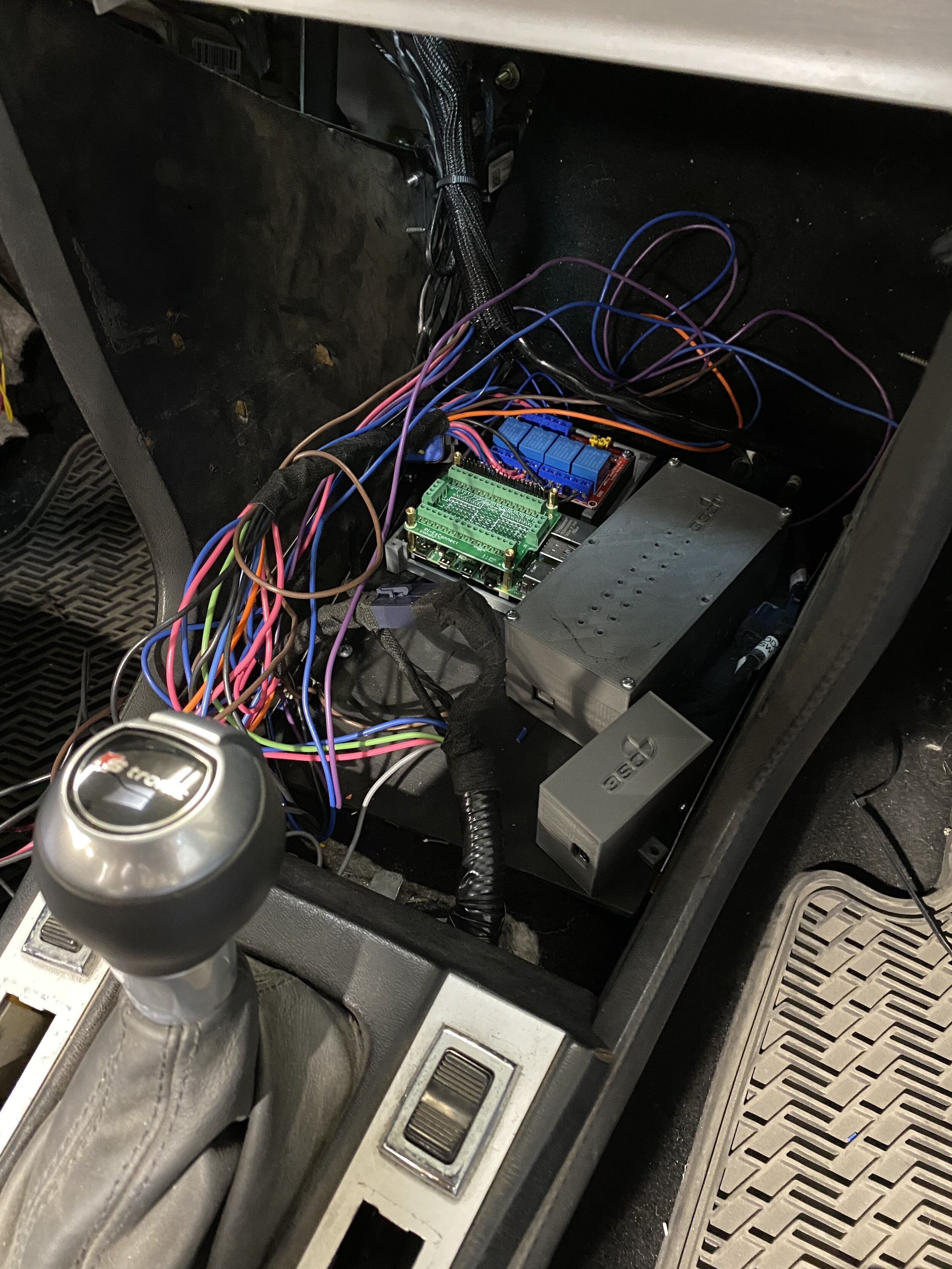
The computers are in place. There is the Raspberry Pi unit which runs the digital display, then two Arduino computers to run the speedometer, fuel and temp gauges, and the odometer.

The wiring for the computers is now complete, though not fully dressed. I then installed the heater and air controls. This is just for show at this point as there is no heater or AC in the car yet. My original plan was to use a 1 inch x 8 inch touchscreen for AC temperature controls as well as seat heater controls and valet mode password activation. But I am starting to get sentimental about the vintage look of the car, so I may stay with the original controls. I’ll live with it for a while before making that decision.
Next up: Install the stereo into the console which will hide the computers and make it look like a complete car. I know the perfect AV guy for the job.
This project continues to elude completion. I assumed that I would buy a car, put a Tesla motor in it and drive the kids to school each morning. Instead, I choose to complicate the project at every turn in order to customize and modify far beyond what was needed. Still, it’s been a fun process and the end of the tunnel of phase one is getting so very near - bringing the car home. There is so much more to be done in phase two.
Until next time - Cheers!
Paul