Add a Dash of Display

When I set out to build an electric classic car I wanted to preserve as much of the classic as I could. I wanted to sneak in my selected modern touches without destroying the vintage nature of the classic BMW coupe.
Now it’s true that I haven’t done that at every turn. It’s easy to spot the places I have chosen to deviate from this standard for various safety, comfort, or performance reasons. But when it comes to the instrument cluster in the dash I wanted to do something very respectful.

Many EV conversions use off-the shelf, non-customizable touchscreens to control and monitor the car. They are intended to bolt into your dash and call it a day. Like this example on the left, they look more like a spreadsheet than anything designed for a car. They provide terrific functionality I’m sure, but I had a vision for something more elegant and usable. I wanted to preserve and repurpose the analog gauges, while sneaking in a digital display. Here is the story:
LETS START WITH THE SPEEDOMETER
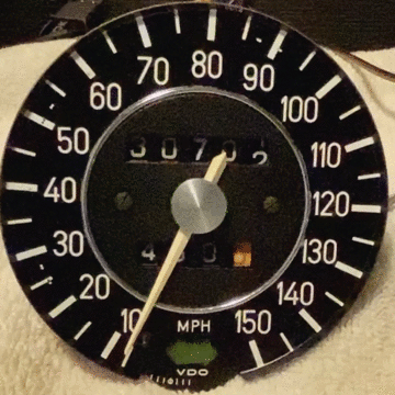
The original speedometer and odometer, like most older cars, runs off of a spinning cable from the transmission. I have no transmission, and thus, no cable. I do have a Tesla controller sending CAN bus information. For those of you who aren’t auto techies, CAN (Controller Area Network) was introduced into cars in the 1990s. Modern cars run almost entirely on CAN messages, from engine management to door locks. We are able to read my Tesla CAN messages and convert that information to control our gauges.
During the COVID lockdown I learned to program up small Arduino computers (and yes they are simple. I am no computer programmer). These are small, inexpensive computers built for hobbyists, but remarkably reliable and can do just about anything. For the BMW a $20 computer, a $20 CAN board and a few $7 stepper motors is all I would need to convert my analog gauges.

Starting with a common stepper motor (this one is used in a lot of GM and other vehicles). I 3D printed an adaptor to convert the small output shaft to the original BMW shaft to which the needle attaches.

I soldered the stepper motor and it’s companion driver board onto a piece of project circuit board (which I first cut to shape).

This old guy can’t solder anything without a magnifying glass and enough light to shine a football stadium.

The finished sub-assembly.

Don’t zoom in too closely, as the soldering looks nice from a distance. I bundled the wires into a clean loom which will exit the speedometer housing.

Looks clean from the front. Notice the smaller output shaft without our adaptor.

This is the back of the BMW speedometer with the old guts removed. Our unit is ready to install.

Our unit is now installed with a 3D printed housing (the 3D printing is a whole story in itself, but let’s just call it magic for now). Another plastic cap is installed before it goes into the Speedometer housing.
Once installed I press the needle on and you can see the motor controls the location based on my computer input.
MOVING TO THE ODOMETER

Inside the speedo/odo housing (or “can” as I call it) I printed a mount to attach the stepper motor, which will drive the odometer mechanism.

I learned how to 3D print, and I use a nice caliper to measure and create my designs. But that doesn’t mean that I get it right the first time. Luckily, these incremental rejects were printed with plant-based recyclable materials.

The stepper motor is now attached to the can. Not shown is a little adaptor I printed to connect the output shaft of our motor to the splined gear of the odometer.

There is a small driver board which runs the stepper motor. It sits behind the can. Notice the two loomed wires going to connectors. One is from our Speedometer assembly we already discussed, the other for the odometer.

Then plastic housing covers the entire assembly. This unit is ready to install into the dash.
FUEL AND TEMPERATURE GAUGES
The original Fuel gauge will now be used to display how much battery charge we have. The Temperature gauge will display the hottest temp among our many temperature readings (we have temperature readings for the motor, inverter, batteries and more).

Thees gauges share the same can, which made fitting the stepper motors tricky.

The motor is installed between two plastic pieces which create this assembly.

This is what it looks like when we are figuring out how to get it to work. Wires everywhere.

We now have computer control of these two gauges.
THE DIGITAL DISPLAY
Since our car has no engine, we have no use for a tachometer. It’s ironic too because when I was “young dumb and broke” the poor-mans version of my cars never had a tachometer. Like my VW Rabbit - I would find myself at a salvage yard buying an instrument cluster from a GTI so I could add a Tach. Thirty years later I am removing my tachometer. Go figure. So if I am going to remove my tach, I need to do something very special.
I began in Illustrator designing a display that would look like it was made for the car. It has a black background so that it blends in with the other gauges. When we put the car into sport mode (using the gear shifter) the upper section changes to an orange background to alert us of the much additional power. The unit tells us our speed, what gear we are in, how much energy is leaving or entering the batteries, as well as basic info such as cruise control, creep mode and more.
After a some research, I figured that a Raspberry Pi computer would be perfect to drive our display. I found a CAN bus unit that would sit on top of the Pi to communicate with our Tesla system.
Finding a display that would fit in our tachometer hole took me several months. There are many affordable displays out there, but finding one just the right size to fit led me to Alibaba. Manufacturers of all sorts of unique electronic components can be found there. Even so it took me two different units from China over 4 months get to the one we see here.

Here is our 5” round display which is fed by a ribbon cable from its driver board, which is fed by the Raspberry Pi via HDMI. The CAN bus '“hat” is sitting to the top right. This is all of the devices required to bring the display to life.
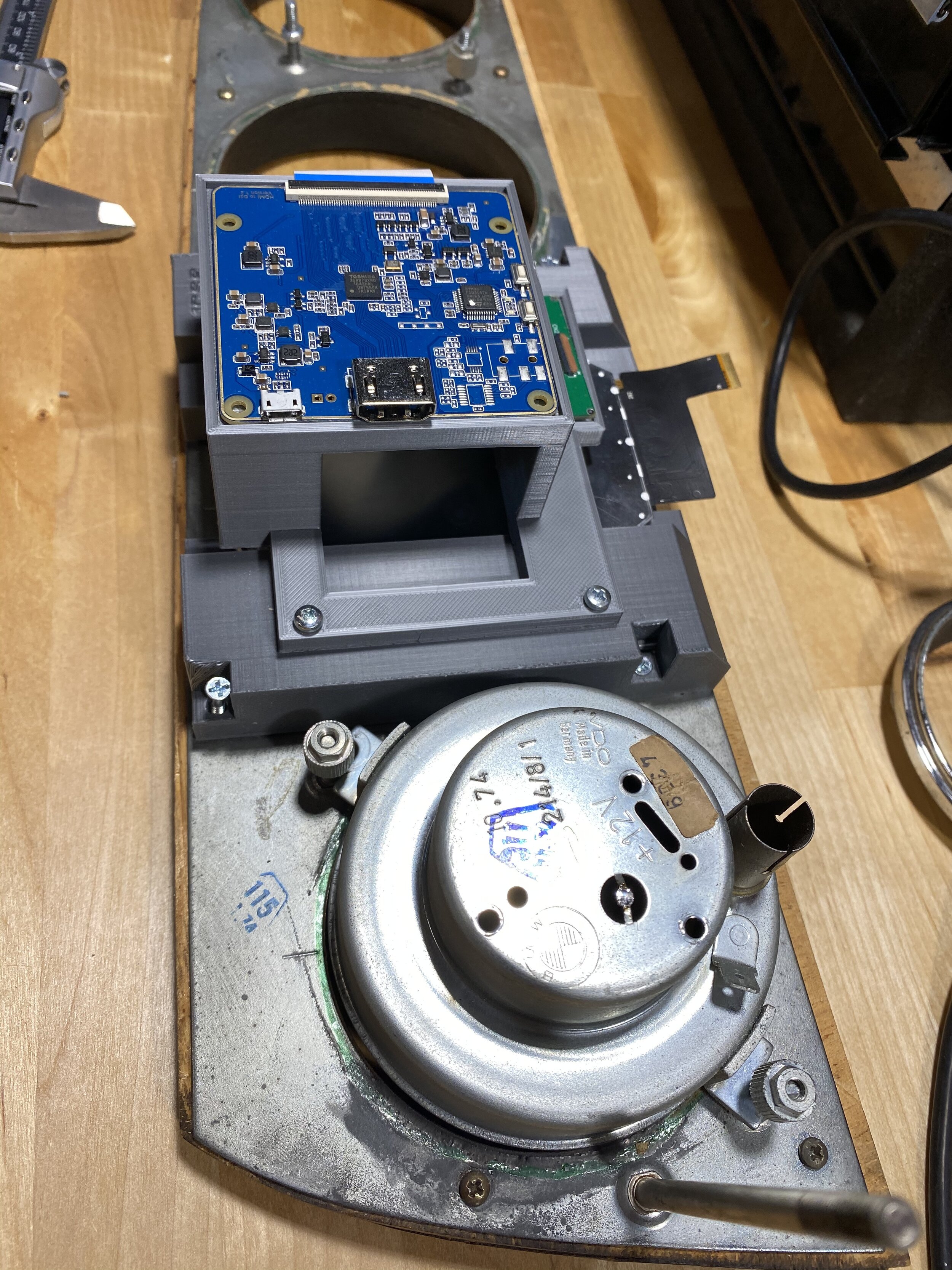
The display is mounted to the back of the instrument cluster through a lot of 3D printing. The display is secured with the base layer, then the driver board to the back of that.
There was no way I was going to learn enough computer coding to put this together. As luck would have it a new friend dropped into place just at the right time. I am helping him with his own EV conversion and he is helping me by programming up my display. He was able to bring to life exactly what I envisioned and I couldn’t be happier.
BRINGING IT ALL TOGETHER
I plan to redo all the wood in the coupe in a later project, but for now I polished the best I could and brought back a lot of life in the 46 year old wood. The chrome polished up nicely as well. I am proud of how this all turned out. Here is a little video of the progression of work on this project. Be sure to watch the end where you see the full animation that occurs when you start the car.


Next up we install our new instrument cluster into the dash. But first there is more work to be done inside the car.
Cheers!
Paul